KDS Power Controller: Difference between revisions
No edit summary |
|||
| Line 12: | Line 12: | ||
<gallery> | <gallery> | ||
File:KDS Power Controller (Top).jpg|Top | File:KDS Power Controller (Top).jpg|Top | ||
File:KDS Power Controller (Bottom).jpg|Bottom | File:KDS Power Controller (Bottom).jpg|Bottom | ||
File:KDS-PowerControler.jpg|Two units | |||
File:KDS Power Controller (power supply being used).jpg|Used supply | File:KDS Power Controller (power supply being used).jpg|Used supply | ||
File:KDS Power Controller PCB (Top).jpg|PCB (Top) | File:KDS Power Controller PCB (Top).jpg|PCB (Top) | ||
Revision as of 21:45, 7 September 2010
Has 8 relays, to control lights, fans, robots etc.
Technical
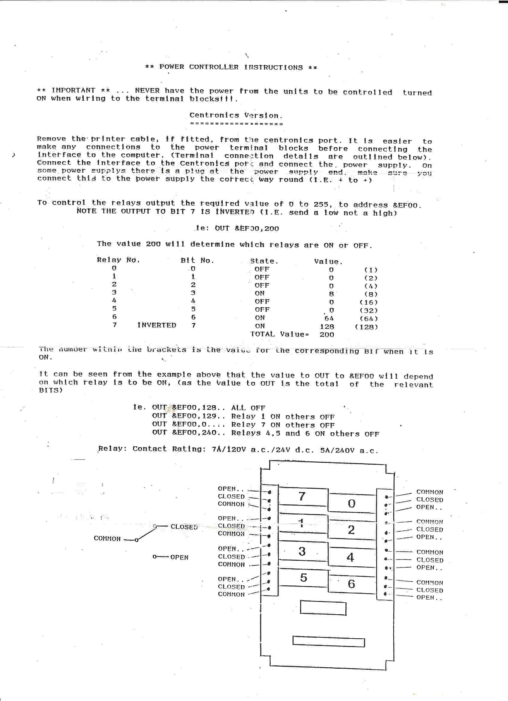
Connects to the 34pin Printer Port. The first 7 relays are controlled by the seven Centronics Data lines, the eight relay is controlled by Centronics Strobe signal.
The relays can be thus controlled by writing an 8bit value to Port EFxxh. Observe that the CPC hardware inverts the strobe bit (so bit7 has opposite meaning as the other bits).
The relays are rated 7A/120VAC, 7A?/24VDC, 5A/240VAC. Each relay has three contacts (common, position 1, and position 2). The relays are driven by an external 7.5V power supply (required since the printer port does not output supply voltages).
Pictures
-
Top
-
Bottom
-
Two units
-
Used supply
-
PCB (Top)
-
PCB (Bottom)
-
PCB (Side)
-
Instructions
.jpg)
.jpg)

.jpg)
.jpg)
.jpg)
.jpg)

Manual
- Instructions (1 page)