Mainboard Versions: Difference between revisions
→CPC6128 version 3 (cost-down): Added new PCB picture by VincentGR |
→CPC464 Prototype: Added Z70100 prototype board and Gate array simulator board. Pictures courtesy of Jorge Selfa. |
||
| Line 48: | Line 48: | ||
|- | |- | ||
|[[File:GA motherboard.JPG|200px]] || || '''Board: Prototype with Gate Array Simulator''' ([[CPC Prototypes|more pictures]])<br>The Gate Array Simulator board (mounted on top of the mainboard, and almost having the same size as the mainboard) contains four 8K EPROMs, and a Gate Array prototype made of several logic chips.<br>In later versions these evolved into a normal 28pin 32K ROM chip, and the custom 40pin Gate Array chip. | |[[File:GA motherboard.JPG|200px]] || || '''Board: Prototype with Gate Array Simulator''' ([[CPC Prototypes|more pictures]])<br>The Gate Array Simulator board (mounted on top of the mainboard, and almost having the same size as the mainboard) contains four 8K EPROMs, and a Gate Array prototype made of several logic chips.<br>In later versions these evolved into a normal 28pin 32K ROM chip, and the custom 40pin Gate Array chip. | ||
|- | |||
|[[File:CPC464_Prototype_Z70100_PCB_Top.jpg|200px]] || [[File:CPC464_Prototype_Z70100_PCB_Bottom.jpg|200px]] || '''Board: PT NO Z70100 Prototype'''<br>Board found along the Gate Array simulator on the "Grey Amstrad" prototype machine.<br>Pictures courtesy of Jorge Selfa. | |||
|- | |||
|[[File:GateArraySimulator_13006-7_PCB_Top.jpg|200px]] || [[File:GateArraySimulator_13006-7_PCB_Bottom.jpg|200px]] || '''Board: Gate Array Simulator 13006/7'''<br>Pictures courtesy of Jorge Selfa. | |||
|- | |- | ||
|} | |} | ||
Revision as of 13:26, 20 March 2022
How to Decode the CPC serial number
This legend will help you define the month and year your CPC rolled out of the factory, as well as the factory itself.
There are two main types of serial number on the back of CPC:
- The first type is located on a small white label. Format is "123456 Kxx-yy"
- The second type is shown directly on the main label and consists of ten digits.
Interpretation of the first type:
"123456 Kxx-yy"
- K is the country of production (K for Korea - South Korea)
- Xx is the plant (31 or 32 are the two codes that typically found).
- Yy is the year and month of leaving the factory. First digit represents the year (4 for 1984, 5 for 1985), second digit represents the month (1 through 9 = January-September, X, Y and Z= October, November and December)
- Finally, the 6-digit number is the actual serial production sequence number fr that factory and year
Examples:
- 93132 K32-54 => Korea factory 32 - April 1985 (a 664)
- 218 167 K32-5X => Korea Factory 31 - October 1985 (a 6128)
- 16201 K31-62 => Korea factory 31 - February 1986 (464)
This numbering was used until February 1986. It relates to a package of 464, 664 and every part of 6128.
Interpretation of the 2nd type:
10 digits (often with a dash between the 3rd and 4th digits)
- 1st digit country code (5 for Korea, Thailand for 6)
- 2nd and 3rd digit = plant code (found: 31 and 32 but also 33, 35, 41 and 71 for Thailand)
- 4th and 5th digits (possibly preceded by a hyphen) = production date (year and month as in the previous system)
- 5-end correspond to the sequence number of the chain of production (per site per month now)
Examples:
- 5326604065 => Korea Factory 31 - June 1986 (it's a 6128)
- 533-7316093 => Korea Factory 31 - March 1987 (it's a 464)
- 671-9408078 => Thailand Factory 71 - April 1989 (it's a 6128)
Boards
CPC464 Prototype
- Size: 405x155 mm
| PCB Top | PCB Bottom | Description |
| Error creating thumbnail: Unable to save thumbnail to destination | Board: Prototype with Gate Array Simulator (more pictures) The Gate Array Simulator board (mounted on top of the mainboard, and almost having the same size as the mainboard) contains four 8K EPROMs, and a Gate Array prototype made of several logic chips. In later versions these evolved into a normal 28pin 32K ROM chip, and the custom 40pin Gate Array chip. | |
| Error creating thumbnail: Unable to save thumbnail to destination | Error creating thumbnail: Unable to save thumbnail to destination | Board: PT NO Z70100 Prototype Board found along the Gate Array simulator on the "Grey Amstrad" prototype machine. Pictures courtesy of Jorge Selfa. |
| Error creating thumbnail: Unable to save thumbnail to destination | Error creating thumbnail: Unable to save thumbnail to destination | Board: Gate Array Simulator 13006/7 Pictures courtesy of Jorge Selfa. |


CPC464 version 1 (original)
- Size: 405x155 mm
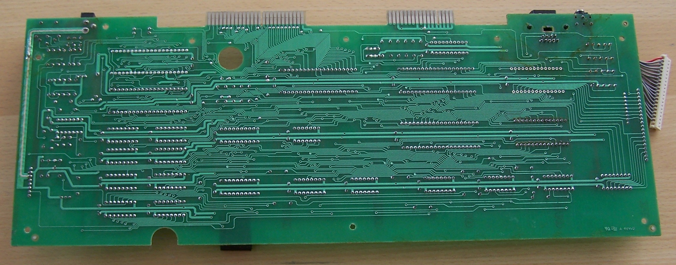
- Big mainboard, old Gate Array with cooling plate and with VCC2; supplied from VCC via two 12 ohm resistors, R138 and R139, which are seen (with white coating) near the cooling plate.
| PCB Top | PCB Bottom | Description |
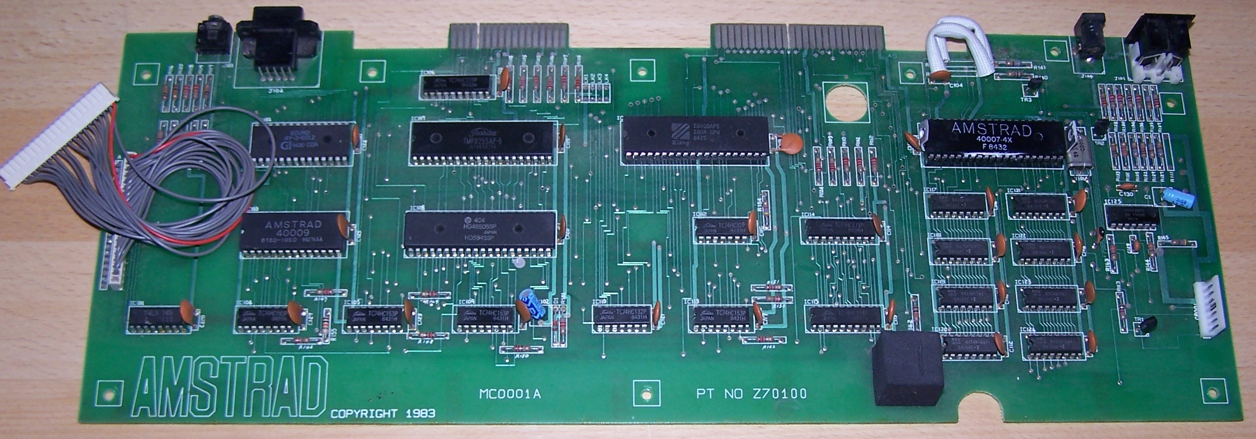
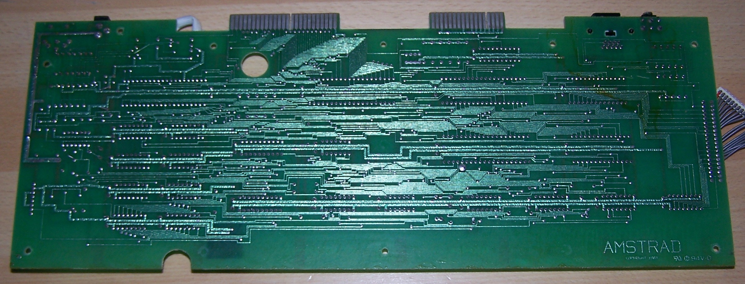
| Error creating thumbnail: Unable to save thumbnail to destination | Error creating thumbnail: Unable to save thumbnail to destination | Board: PT NO Z70100, without any "MCnnnn" code, Copyright 1983 Original version. Real wires going to keyboard. another picture. |
| Error creating thumbnail: Unable to save thumbnail to destination | Error creating thumbnail: Unable to save thumbnail to destination | Board: PT NO 270100, MC0001A, Copyrigh 1983 Same as "Z70100 MC0001A", but with uncommon text layer: labeled "270100" (not "Z70100"), says "Copyrigh" (not "Copyright"), and, unlike all other boards, its text has slashed zeroes. another picture. |
| Error creating thumbnail: Unable to save thumbnail to destination | Error creating thumbnail: Unable to save thumbnail to destination | Board: PT NO Z70100, MC0001A, Copyright 1983 Keyboard connector now has two rows of soldering points; probably intended to support two different connectors: The old PCB keyboard with wires, and the new CPC664-style 19pin single-foil "membrane" keyboard. More Pictures here, here and here. |
_GA40007-4.jpg)
_GA40007-4.jpg)


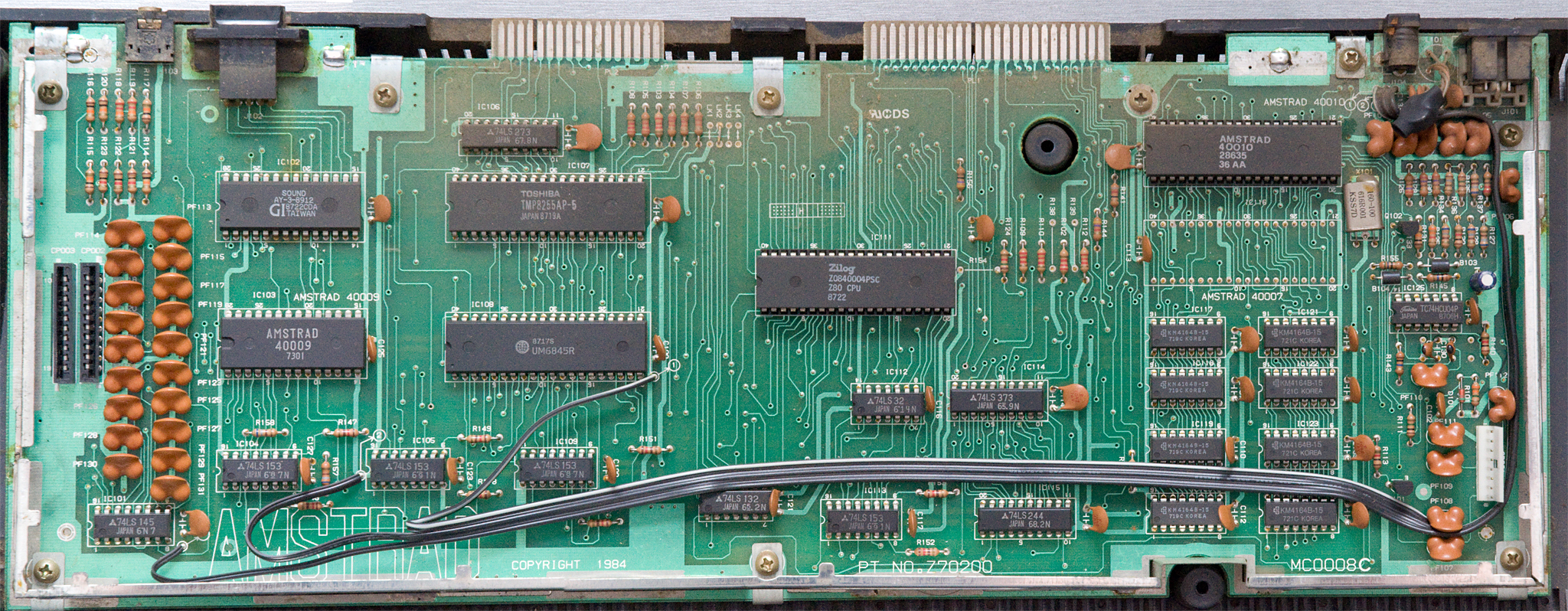
CPC464 version 2 (new gate array)
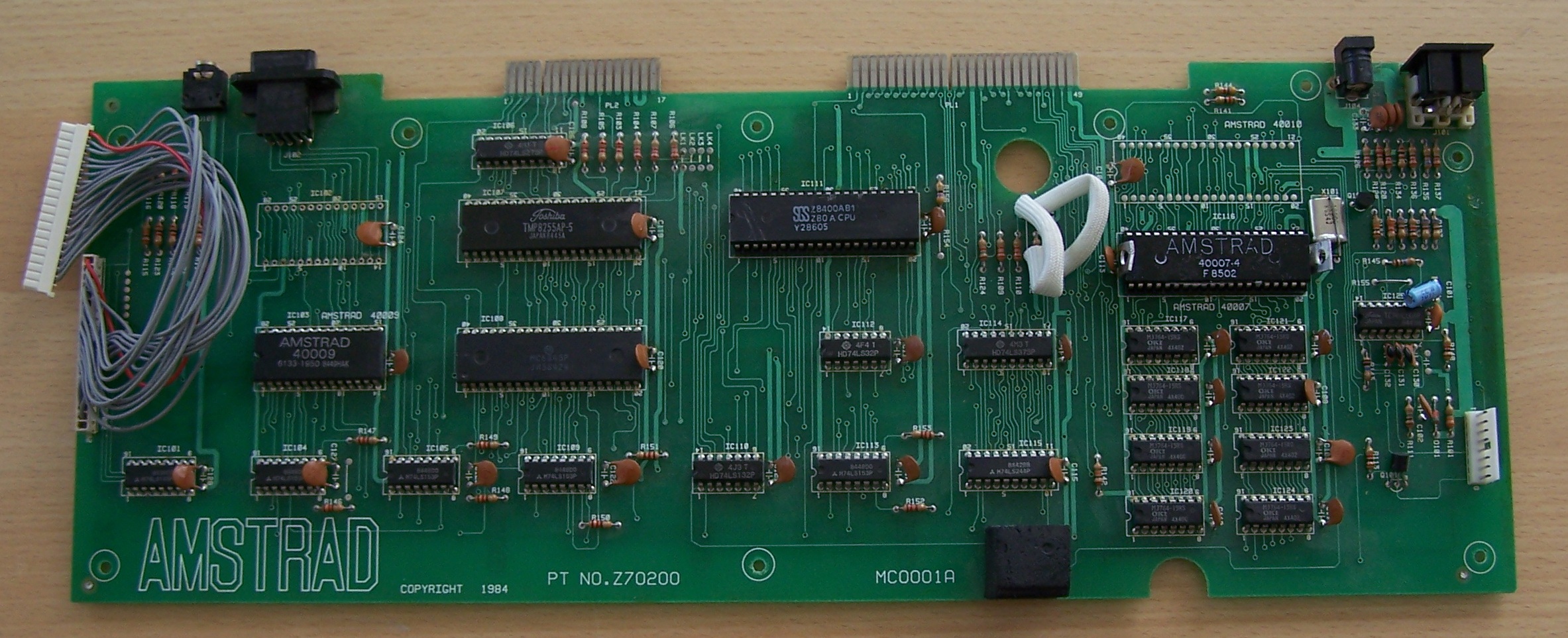
- Size: 405x152 mm
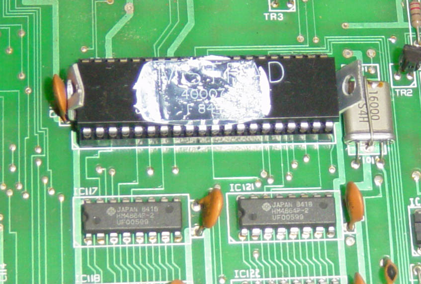
- Separate soldering points for old and new Gate Array (with changed pin-outs).
- New connector for new 6128-style 2x10pin dual-foil membrane keyboards (still has optional soldering points old 19pin foils).




.jpg)
.jpg)

.jpg)
.jpg)


.jpg)
.jpg)

_GA40008.jpg)
_GA40008.jpg)



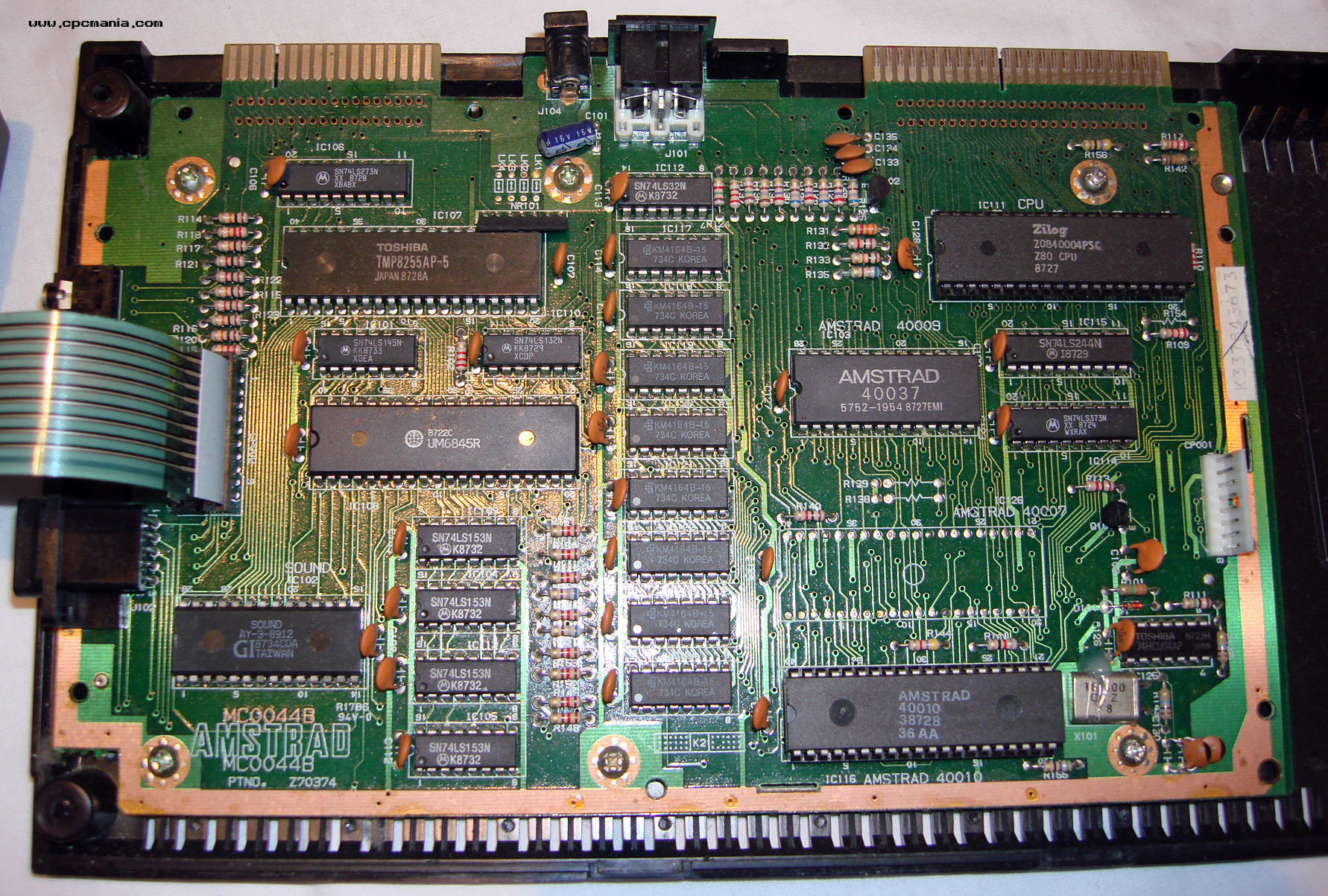
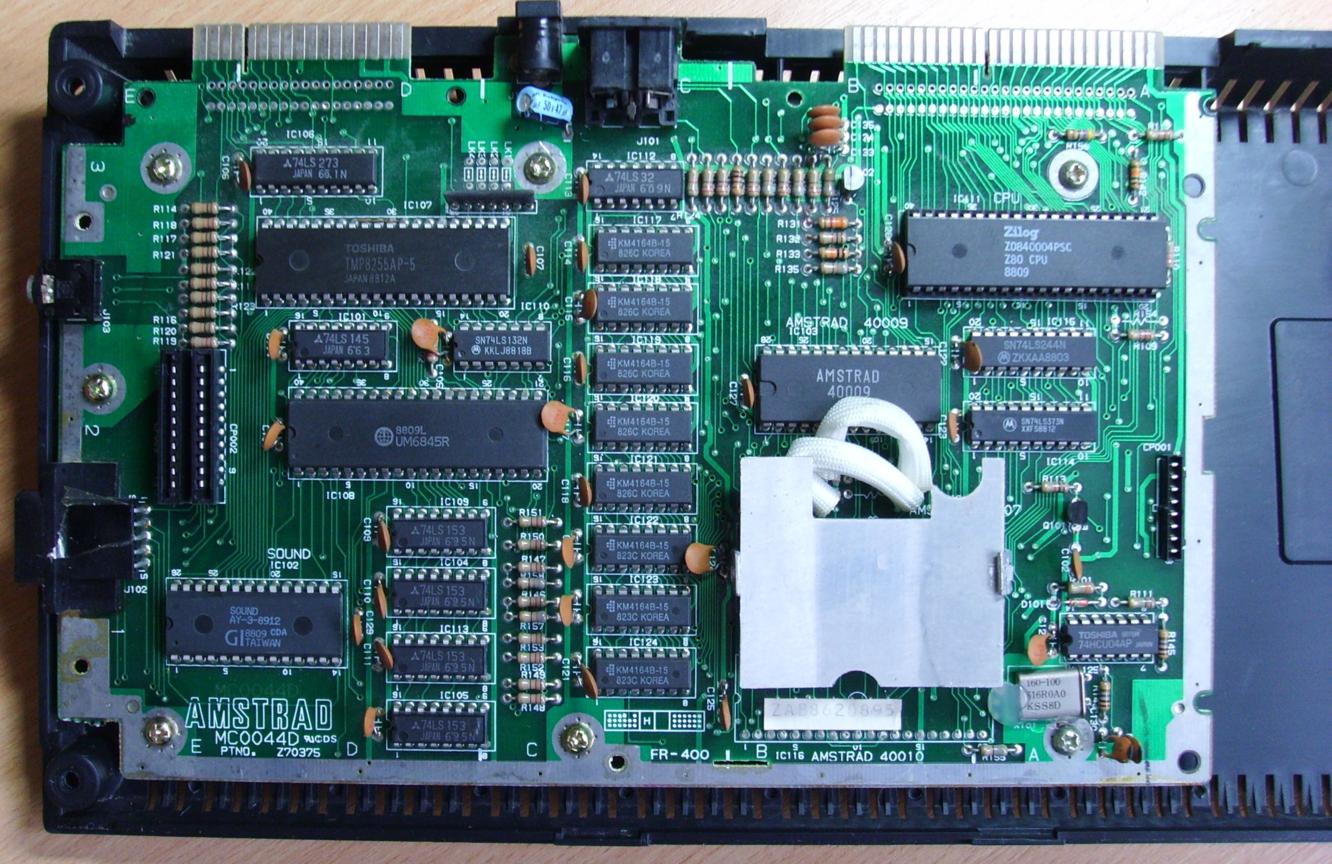
CPC464 version 3 (medium-sized)
- Size: 240x150 or 238x145 mm
- Medium sized mainboard. Same components as previous version, but arranged more tightly. Joystick/stereo moved to left side.
- Can be optionally fitted with Amphenol connectors (instead of Edge connectors, as far as known, this option was never used for the 464). The screw-holes have contacts for optional shielding-plate (this option was used in German Schneider models).



.jpg)
.jpg)


.jpg)
.jpg)


CPC464 version 4 (cost-down)
- Size: 237x108 mm
| PCB Top | PCB Bottom | Description |
| Error creating thumbnail: Unable to save thumbnail to destination | Error creating thumbnail: Unable to save thumbnail to destination | Board: PT NO Z80329, MC0099A, Copyright 1988 Tiny mainboard. Uses 100pin SMD Gate Array (combines the old Gate Array, CRTC, and some FDC/DRAM/RESET logic in one chip). Here is another picture. |
.jpg)
.jpg)

CPC472
- Size: 405x155 mm
| PCB Top | PCB Bottom | Description |
| Error creating thumbnail: Unable to save thumbnail to destination | Error creating thumbnail: Unable to save thumbnail to destination | Board: PT NO Z70200, MC0002C, Copyright 1984 with MS0043A daughterboard (more pictures) The Spanish CPC472, with nonfunctional 8K RAM on the daughterboard |
| Error creating thumbnail: Unable to save thumbnail to destination | Error creating thumbnail: Unable to save thumbnail to destination | Board: PT NO Z70200, MC0002D, Copyright 1984 with MS0043A daughterboard (more pictures) The Spanish CPC472, with nonfunctional 8K RAM on the daughterboard |


CPC664
- Size: 475x155 mm
| PCB Top | PCB Bottom | Description |
| Error creating thumbnail: Unable to save thumbnail to destination | Error creating thumbnail: Unable to save thumbnail to destination | Board: PT NO Z70205, MC0005A 8pin FDC Data Separator |
| Error creating thumbnail: Unable to save thumbnail to destination | Error creating thumbnail: Unable to save thumbnail to destination | Board: PT NO Z70205, MC0005B Another 664 version, found in German Schneider CPCs (but might be also used in other countries?) This board version typically includes a small patch: A resistor soldered between Pin9 (A0) and Pin14 (/CASADDR) of IC105. The patch is also seen here. The resistor is labeled as R160 in the schematic, but isn't labeled on the PCB, so it was apparently added after designing the PCB. Here is another picture. |


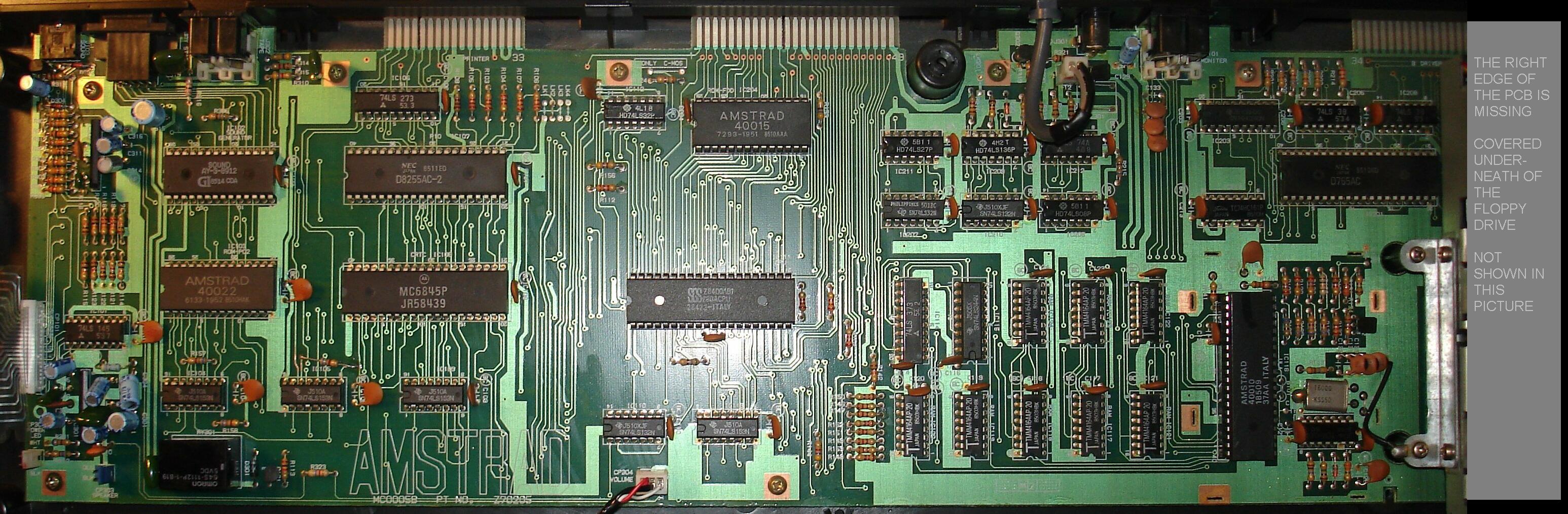
CPC6128 version 1 (8pin data separator, solder points for old and new gate array)
- Size: 320x155 mm
| PCB Top | PCB Bottom | Description |
| Error creating thumbnail: Unable to save thumbnail to destination | Error creating thumbnail: Unable to save thumbnail to destination | Board: PT NO Z70210, MC0009A Separate soldering points for old and new Gate Array (as far as known, the old Gate Array was never used in 6128 though, only in 464). 8pin FDC Data Separator. Can be fitted with Amphenol connectors (as used in German CPCs) (instead of edge connectors). Here's another picture. |
| Error creating thumbnail: Unable to save thumbnail to destination | Board: PT NO Z70210, MC0009A Centronics Version Separate soldering points for old and new Gate Array. | |
| Error creating thumbnail: Unable to save thumbnail to destination | Error creating thumbnail: Unable to save thumbnail to destination | Board: PT NO Z70210, MC0009B Separate soldering points for old and new Gate Array. |
| Error creating thumbnail: Unable to save thumbnail to destination | Error creating thumbnail: Unable to save thumbnail to destination | Board: PT NO Z70210, MC0009C Separate soldering points for old and new Gate Array. |
| Error creating thumbnail: Unable to save thumbnail to destination | Error creating thumbnail: Unable to save thumbnail to destination | Board: PT NO Z70210, MC0012A Centronics Version Separate soldering points for old and new Gate Array. |
| Error creating thumbnail: Unable to save thumbnail to destination | Error creating thumbnail: Unable to save thumbnail to destination | Board: PT NO Z70210, MC0012B Centronics Version Separate soldering points for old and new Gate Array. |
| Error creating thumbnail: Unable to save thumbnail to destination | Error creating thumbnail: Unable to save thumbnail to destination | Board: PT NO Z70270, MC0016A Centronics Version Separate soldering points for old and new Gate Array. Courtesy of Noel Llopis. |
.jpg)
.jpg)


.jpg)
.jpg)
.jpg)
.jpg)
.jpg)
.jpg)


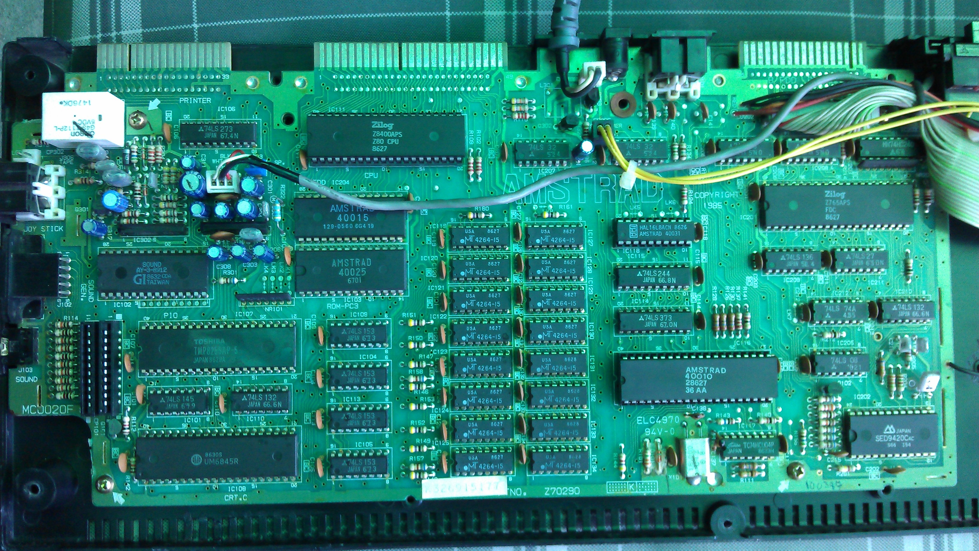
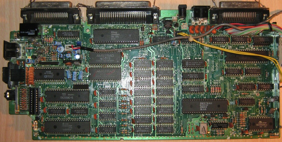
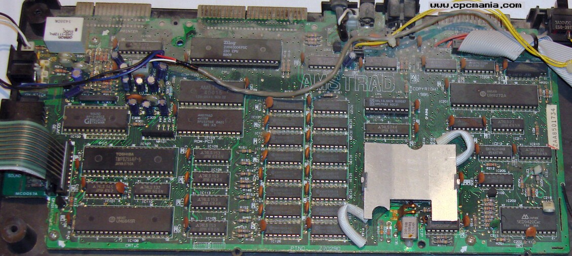
CPC6128 version 2 (24pin data separator, solder points for new gate array only)
- Size: 320x155 mm
.jpg)
.jpg)
.jpg)
.jpg)


.jpg)
.jpg)
.jpg)
.jpg)
.jpg)
.jpg)


.jpg)
.jpg)

.jpg)
.jpg)

.jpg)
.jpg)
.jpg)
.jpg)
.jpg)
.jpg)

CPC6128 version 3 (cost-down)
- Size: 310x145 mm
| PCB Top | PCB Bottom | Description |
| Error creating thumbnail: Unable to save thumbnail to destination | Error creating thumbnail: Unable to save thumbnail to destination | Board: PT NO Z80330, MC0100A (1988) Uses 100pin SMD Gate Array (combines the old Gate Array and PAL, CRTC, and some FDC/DRAM/RESET logic in one chip). Can be fitted with four 64Kx4 RAM chips (or the normal sixteen 64Kx1 RAM chips) Printer port consists of 74LS174+74LS175 (instead of 74LS273) More pictures here and here. |
.jpg)
.jpg)


CPC 464+
- Size: 282x142 mm
- Same mainboard is used in 464+ and 664+ (though not all components installed in 464+, and with different LK Links.
- Uses 160pin SMD Gate Array (ASIC).
| PCB Top | PCB Bottom | Description |
| Error creating thumbnail: Unable to save thumbnail to destination | Error creating thumbnail: Unable to save thumbnail to destination | Board: 2700-016P-3, MC0122B, Copyright 1990 IC16 is 74HCT02 with two extra resistors between pins 2+14 and 3+4 extra diodes near R71-R75 (below right edge of expansion port) (other picture) |
| Error creating thumbnail: Unable to save thumbnail to destination | Board: 2700-016P-3, MC0122C, Copyright 1990 IC16 is 74LS27 without extra resistors other extra diodes near R71-R75, and R73 is not installed | |
| Error creating thumbnail: Unable to save thumbnail to destination | Board: 2700-016P-3, MC0122D, Copyright 1990 New D29/D30 (instead of the "extra" diodes near R71-R75) |


CPC 6128+
- Size: 282x142 mm
- Same mainboard is used in 464+, but with additional components installed (extra RAM chips, FDC chips, internal/external floppy connectors, and with different LK Links).
- Uses 160pin SMD Gate Array (ASIC), and 24pin data separator.
| PCB Top | PCB Bottom | Description |
| Error creating thumbnail: Unable to save thumbnail to destination | Error creating thumbnail: Unable to save thumbnail to destination | Board: 2700-016P-3, MC0122C, Copyright 1990 (other picture)(other picture) |
| Error creating thumbnail: Unable to save thumbnail to destination | Error creating thumbnail: Unable to save thumbnail to destination | Board: 2700-016P-3, MC0122D, Copyright 1990 (other picture) |
| Error creating thumbnail: Unable to save thumbnail to destination | Board: 2700-016P-3, MC0122E, Copyright 1990 |


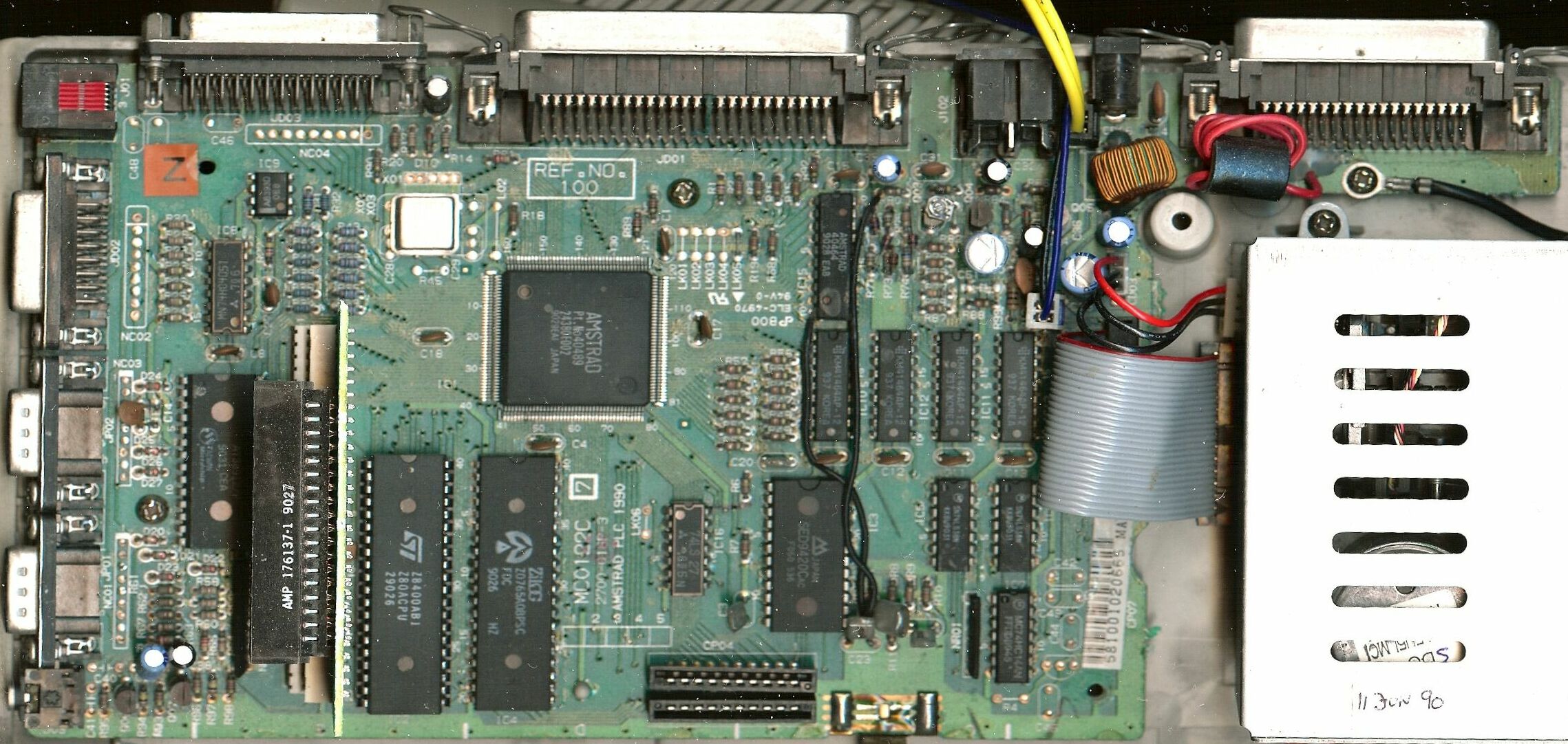


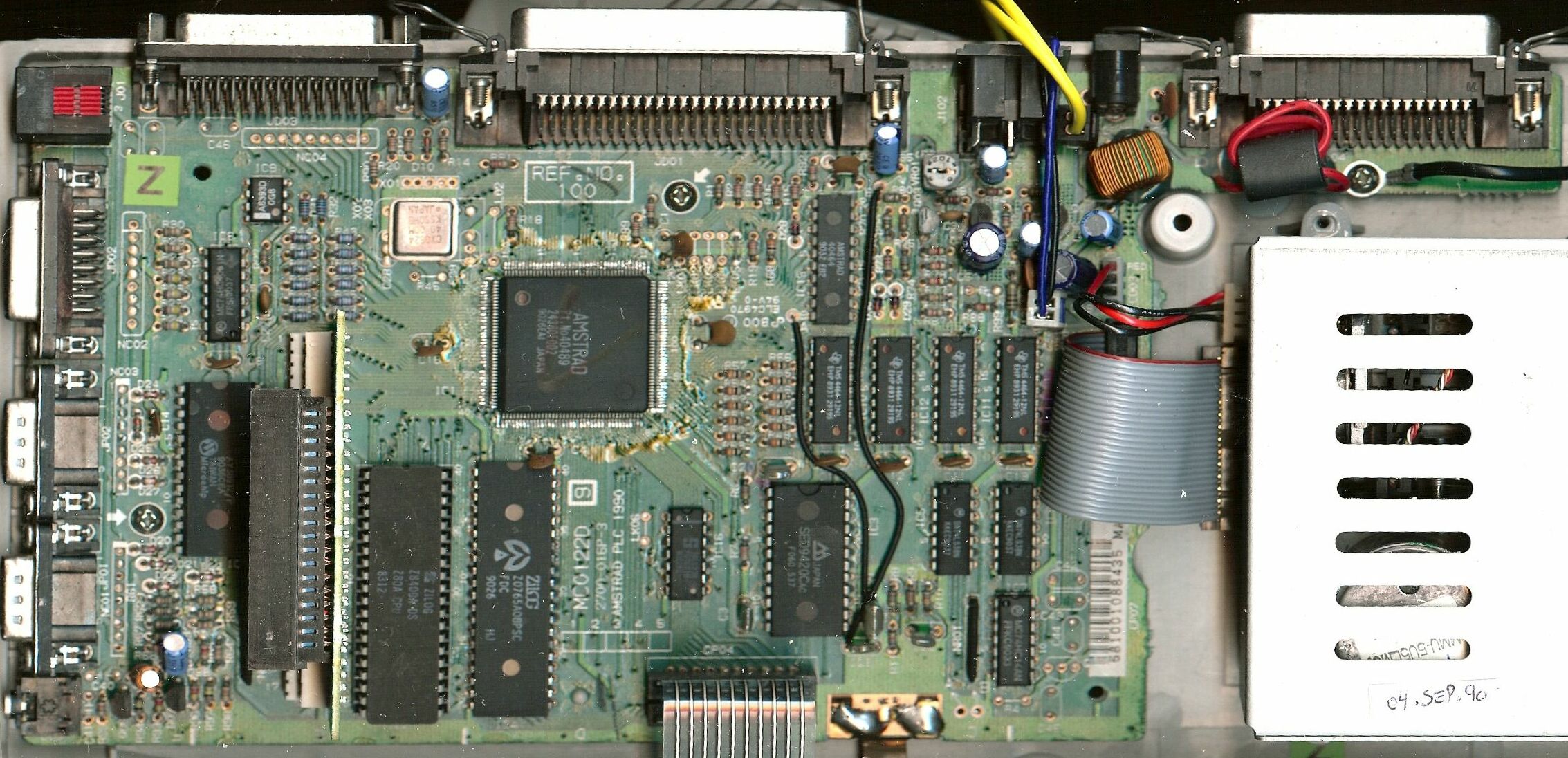

Other Plus versions are shown in the Service Manuals (Plus series, page 5 = MC0122B, and page 16 = MC0122A).
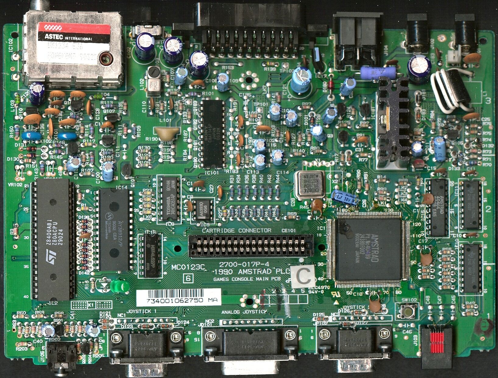
GX4000
- Size: 205x150 mm
- Same chipset as CPC+, but lacks Keyboard, Expansion Port, Printer Port, Tape/Disc Interfaces.
- Additional Scart Connector and TV Modulator.
.jpg)
.jpg)
_NoMod.jpg)
_NoMod_.jpg)
.jpg)
.jpg)

_NoMod.jpg)
_NoMod.jpg)


.jpg)
.jpg)

_NoMod.jpg)
_NoMod.jpg)
.jpg)
.jpg)

.jpg)
.jpg)


Another GX4000 board (2700-017P-3, MC0123A, Copyright 1990) is shown in Service Manuals (Plus series, page 24 and page 32/france).
System Cartridge (BIOS of CPC+) and Game Cartridges
- Size: 52x60 mm (more pictures)


DDI-1
- Size: 160x65 mm
| PCB Top | PCB Bottom | Description |
| Error creating thumbnail: Unable to save thumbnail to destination | Error creating thumbnail: Unable to save thumbnail to destination | Board: MF0004B, ISS3, (C) Amstrad 1984 (more pictures) 20pin FDC Data Separator |


Clones
| PCB Top | PCB Bottom | Description |
| Error creating thumbnail: Unable to save thumbnail to destination | Error creating thumbnail: Unable to save thumbnail to destination | KC Compact (more pictures) Size: 370x200 mm East german CPC464 clone (CPC 464-style 64K RAM, Tape Drive, though using 6128 BIOS version) |
| Error creating thumbnail: Unable to save thumbnail to destination | Error creating thumbnail: Unable to save thumbnail to destination | Board: PATISONIC ALESTE 520EX 01.003 (more pictures) Size: ???x??? mm Russian CPC128 clone with some additonal features (512K RAM, additional video modes, RTC, SIO, etc.) |


Notes
- The last letter of the PT NO Znnnnn, MCnnnnX board numbers does not seem to indicate a revision (the boards appear to be identical regardless of that letter, as long as the other digits are same). So, the last letter may indicate the manufacturing date or manufacturing location.
To Do
- http://cpcwiki.eu/forum/index.php/topic,678.msg9509.html#msg9509 - some more precision values for Mainboard sizes. Add them to this page!
See also
- Amstrad part numbers - Part Numbers for PCBs and Chips
- Keyboard Versions
- Schematics
- Service Manuals - (cost-down 6128 is in the Amendment manual)
Forum
- http://cpcwiki.eu/forum/index.php/topic,678.0.html - CPC Mainboard Versions related