Amstrad External Disk Drive: Difference between revisions
Cpcmaniaco (talk | contribs) |
|||
| (26 intermediate revisions by 8 users not shown) | |||
| Line 1: | Line 1: | ||
'''Amstrad''' made two different disk drives for the Amstrad/Schneider CPC range: | '''Amstrad''' made two different [[disk drives]] for the Amstrad/Schneider CPC range: | ||
* DDI-1 | * DDI-1: a set consisting of the real DDI-1 (= Disk Drive Interface) and a FD-1 3" disk drive, as well as the CP/M 2.2 license and disk.<br> This set was for the CPC464 which didn't have a built-in [[765 FDC]] disk controller. | ||
* FD-1: a 3" disk drive as secondary disk drive unit for the CPC664, CPC6128, and for the CPC464 with DDI-1 | |||
All drives are for use with [[CF2 Compact Floppy Disc]] 3" discs. | |||
There was no official external disk drive for the 6128Plus or even the 464Plus. The difference between a CPC664/CPC6128 and a 6128Plus was simply a changed pin-out which can easily be solved by a new plug on the disk drive's cable. | |||
The 464Plus was harder to equip with a disk drive. Although the pin-out of the expansion port was left unchanged, the DDI-1 cannot be used on the 464Plus without modifications (see [[Connecting a Disc Interface to CPC464+]]). | |||
== Technical Details == | |||
The two disk drives were identical. The only difference was that the DDI-1 shipped with controller, manual and CP/M 2.2 on one disk. | |||
The | The disk drives were jumpered (more accurately, soldered) to react on both drive select lines, A: and B:. | ||
The | The cable decided which drive became A: and which one became B: : | ||
* On the CPC664 and CPC6128 computers, DRIVE SELECT 0 was not connected on the external connector, so the drive could only become drive B: on these systems. | |||
* For the DDI-1, DRIVE SELECT 0 was only wired to the outermost connector of the attached cable, while the inner connector was wired to DRIVE SELECT 1 only, thus the drive at the cable's end always became A: while the other one became drive B: accordingly. | |||
Note that the drive also powered the DDI-1 interface when used together with it. Certain pins documented as N/C in the CPC664/CPC6128 manual in fact carry +5V from the drive to the controller. | |||
The main reason for this was that you couldn't connect a standard drive with a more common format (5¼" in the beginning, 3½" later and today) and thus cheaper disks as drive A: without modifications, as the DDI-1 wouldn't work without the power fed from the FD-1. | |||
Details on [[AMSDOS]], Amstrad's implementation of [[CP/M]] can be found in [[Soft158A:_DDI-1_Firmware_-_The_Complete_CPC_464_DOS_ROM_Specification|DDI-1 Firmware SOFT158A]]. | |||
== Pictures == | == Pictures == | ||
<gallery | <gallery> | ||
Image:Fd-1.jpg|FD-1 (disc drive) | |||
Image: | Image:DDI-1 Tomdalby.jpg|DDI-1 (disc interface) | ||
Image:DDI-1 ISS3 MF0004B.jpg|DDI-1 (pcb) | |||
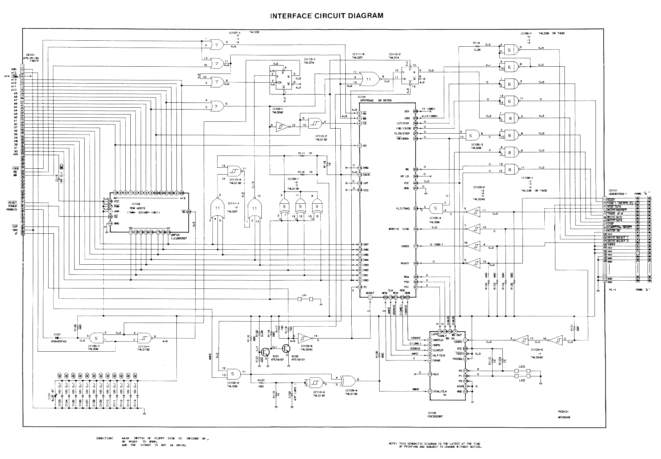
Image:DDI Schematic.png|DDI-1 (schematic) | |||
Image:Gerald DDI-1 MF0004B.jpg|DDI-1 (top) | |||
Image:Gerald DDI-1 MF0004B-Back with ABBA switch mod.jpg|DDI-1 (bottom) | |||
Image:DDI1_PCB_Top.jpg|MF0004B Models 9,5,3 and 1 PCB (top) | |||
Image:DDI1_PCB_Bottom.jpg|MF0004B Models 9,5,3 and 1 PCB (bottom) | |||
Image:ACU850102 -012.jpg|Advert (ACU Jan 1985) | |||
Image:Amstrad Computer User8504 044.jpg|Advert (ACU Apr 1985) | |||
Image:DDI-1_cable.jpg| DDI-1 cable pinout | |||
Image:DDI-1.jpg|DDI-1 - complete with manual, interface, FD-1 drive & CF-2 discs | |||
</gallery> | </gallery> | ||
| Line 50: | Line 59: | ||
* [http://www.cpcwiki.eu/manuals/ddi-1.zip Amstrad DDI-1 (English) Manual] | * [http://www.cpcwiki.eu/manuals/ddi-1.zip Amstrad DDI-1 (English) Manual] | ||
* [http://www.cpcwiki.eu/manuals/DDI-1.es.rar Amstrad DDI-1 (Spanish) Manual] | * [http://www.cpcwiki.eu/manuals/DDI-1.es.rar Amstrad DDI-1 (Spanish) Manual] | ||
* [[Media:DDI-1_Handbuch.pdf]] (German) Manual | |||
== Service Manual == | == Service Manual == | ||
| Line 55: | Line 65: | ||
* [http://www.cpcwiki.eu/manuals/DDI-1%20FD-1%20Service%20Manual.en.rar Amstrad DDI-1 FD-1 Service Manual] | * [http://www.cpcwiki.eu/manuals/DDI-1%20FD-1%20Service%20Manual.en.rar Amstrad DDI-1 FD-1 Service Manual] | ||
[[ | == Datasheets == | ||
* [[Media:UPD765 Datasheet OCRed.pdf]] - uPD765 disc controller | |||
* [[Media:FDC9229BT Datasheet.pdf]] - FDC9229BT data separator (that usually assists the uPD765 chip) | |||
* [[Media:DDI Schematic.png]] - DDI-1 Schematic (disc interface for CPC464) | |||
[[Category:Peripherals]] [[Category:Manual]][[Category:DATA Storage]][[Category:CPC Internal Components]][[Category:Amstrad Products]] | |||
Latest revision as of 10:30, 6 May 2018
Amstrad made two different disk drives for the Amstrad/Schneider CPC range:
- DDI-1: a set consisting of the real DDI-1 (= Disk Drive Interface) and a FD-1 3" disk drive, as well as the CP/M 2.2 license and disk.
This set was for the CPC464 which didn't have a built-in 765 FDC disk controller.
- FD-1: a 3" disk drive as secondary disk drive unit for the CPC664, CPC6128, and for the CPC464 with DDI-1
All drives are for use with CF2 Compact Floppy Disc 3" discs.
There was no official external disk drive for the 6128Plus or even the 464Plus. The difference between a CPC664/CPC6128 and a 6128Plus was simply a changed pin-out which can easily be solved by a new plug on the disk drive's cable.
The 464Plus was harder to equip with a disk drive. Although the pin-out of the expansion port was left unchanged, the DDI-1 cannot be used on the 464Plus without modifications (see Connecting a Disc Interface to CPC464+).
Technical Details
The two disk drives were identical. The only difference was that the DDI-1 shipped with controller, manual and CP/M 2.2 on one disk.
The disk drives were jumpered (more accurately, soldered) to react on both drive select lines, A: and B:.
The cable decided which drive became A: and which one became B: :
- On the CPC664 and CPC6128 computers, DRIVE SELECT 0 was not connected on the external connector, so the drive could only become drive B: on these systems.
- For the DDI-1, DRIVE SELECT 0 was only wired to the outermost connector of the attached cable, while the inner connector was wired to DRIVE SELECT 1 only, thus the drive at the cable's end always became A: while the other one became drive B: accordingly.
Note that the drive also powered the DDI-1 interface when used together with it. Certain pins documented as N/C in the CPC664/CPC6128 manual in fact carry +5V from the drive to the controller. The main reason for this was that you couldn't connect a standard drive with a more common format (5¼" in the beginning, 3½" later and today) and thus cheaper disks as drive A: without modifications, as the DDI-1 wouldn't work without the power fed from the FD-1.
Details on AMSDOS, Amstrad's implementation of CP/M can be found in DDI-1 Firmware SOFT158A.
Pictures
-
FD-1 (disc drive)
-
DDI-1 (disc interface)
-
DDI-1 (pcb)
-
DDI-1 (schematic)
-
DDI-1 (top)
-
DDI-1 (bottom)
-
MF0004B Models 9,5,3 and 1 PCB (top)
-
MF0004B Models 9,5,3 and 1 PCB (bottom)
-
Advert (ACU Jan 1985)
-
Advert (ACU Apr 1985)
-
DDI-1 cable pinout
-
DDI-1 - complete with manual, interface, FD-1 drive & CF-2 discs


Covers
- Manuals
-
(English) User Manual
-
(German) User Manual
-
(Spanish) User Manual
-
Service Manual

_Manual.jpg)


Manuals
- Amstrad DDI-1 (English) Manual
- Amstrad DDI-1 (Spanish) Manual
- Media:DDI-1_Handbuch.pdf (German) Manual
Service Manual
Datasheets
- Media:UPD765 Datasheet OCRed.pdf - uPD765 disc controller
- Media:FDC9229BT Datasheet.pdf - FDC9229BT data separator (that usually assists the uPD765 chip)
- Media:DDI Schematic.png - DDI-1 Schematic (disc interface for CPC464)